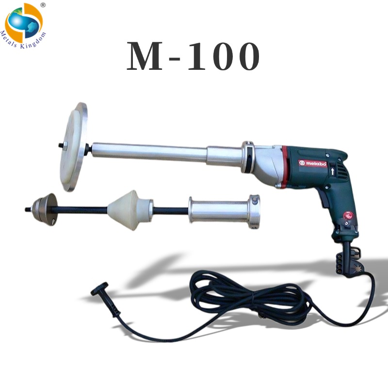
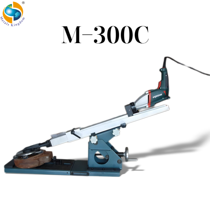
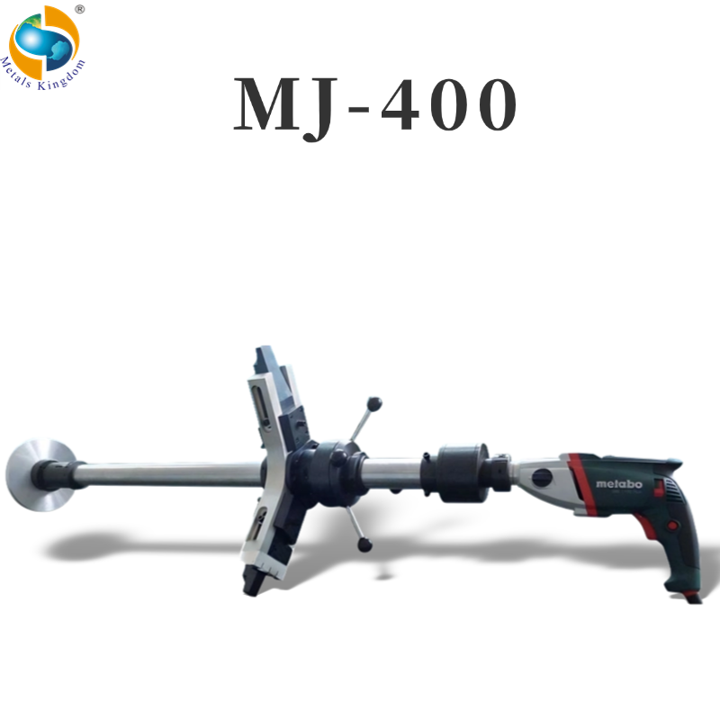
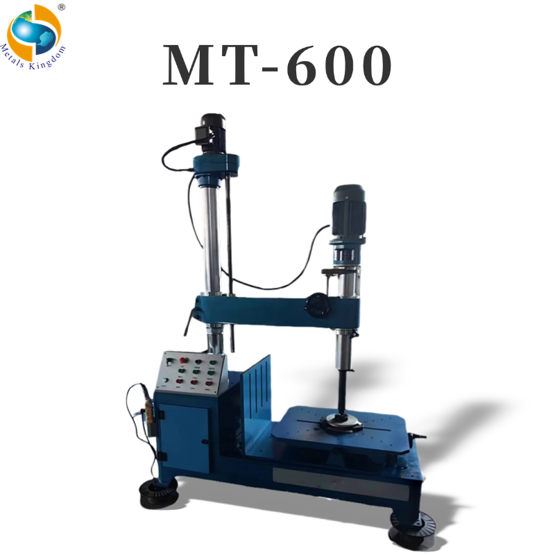
Portable pipe cutting and beveling machines help maintenance teams prepare accurate weld joints directly at the jobsite. However, the quality of the finished bevel depends on more than the machine itself. Incorrect pipe data, poor clamping, unsuitable tooling, limited access, or unstable feeding can cause chatter, an uneven root face, an incorrect bevel angle, or unnecessary rework.
The following checklist gives supervisors, technicians, and procurement teams a practical method for preparing a cold cutting and pipe beveling operation before machining begins.
1. Confirm the Pipe and Joint Requirements
Start with verified pipe information rather than an approximate field measurement. Record the outside diameter, inside diameter, wall thickness, material grade, ovality, corrosion condition, and any coating that may interfere with mounting.
The required weld preparation must also be clear. Confirm the bevel angle, root face, internal counterbore, compound bevel profile, and allowable dimensional tolerances. If a welding procedure specification is available, the machining requirements should be checked against it before selecting the equipment and cutting tools.
For replacement sections, compare the existing pipe with the new spool. Even when the nominal sizes match, differences in actual wall thickness or ovality may affect tool selection and alignment.
If the existing pipe end is flame-cut, heavily corroded, or deformed, allow sufficient machining stock. The first machining pass may need to remove an irregular or hardened surface before the final bevel can be produced.
2. Select the Correct Mounting Method
Portable pipe beveling machines are commonly mounted from the pipe inside diameter or clamped around the outside diameter.
An ID-mounted machine is useful when the pipe exterior is obstructed and the bore provides enough clean, round clamping area. It is often selected for pipe-end beveling, facing, and internal counterboring.
An OD-mounted split-frame machine is normally preferred when cutting and beveling must be completed in one setup. It is also suitable when the pipe end is unavailable for internal mounting or when the pipe section must be separated before weld preparation.
Check the actual working envelope, not only the nominal machining range. Nearby elbows, flanges, supports, insulation, structural steel, and adjacent pipelines may restrict the machine's rotation or prevent installation.
The operator also needs sufficient space to install the machine, adjust the tool slide, connect the drive, control the feed, and observe the cutting process.
3. Verify Clamping and Pipe Stability
The pipe and machine must remain stable throughout the operation. Remove loose scale, dirt, coating, grease, or weld spatter from the mounting area before installing the equipment.
Inspect the clamping shoes, expansion blocks, split-frame joints, locating surfaces, and fasteners for wear or damage. Tighten the mounting system evenly and verify concentricity before allowing the cutting tool to contact the pipe.
Uneven clamping can cause the machine to move around the pipe axis, resulting in variations in bevel angle and root-face thickness. Excessive clamping force may also damage thin-wall pipe or distort an already weakened pipe section.
Support the pipe section on both sides of the planned cut when its weight could cause movement, bending, or tool pinching. Before a complete separation cut, confirm how the free pipe section will be restrained, lifted, and removed.
The portable cutting machine must never be used as a pipe support.
4. Match the Tooling to the Pipe Material
Tool material and geometry should match the pipe material, wall thickness, surface condition, and required bevel profile.
Carbon steel, stainless steel, alloy steel, duplex steel, and hard-facing materials may require different tool materials, cutting speeds, and feed rates. A heavily oxidized flame-cut surface may also require a more robust first tool than a clean machined pipe end.
Inspect every tool bit or insert for chips, cracks, incorrect grinding, and secure seating. Confirm that the cutting and beveling tools are installed in the correct sequence and that their cutting paths will not interfere.
For simultaneous cutting and beveling, the separation tool and beveling tool must be positioned correctly relative to each other. Incorrect tool placement may create excessive load, poor chip evacuation, or an incomplete bevel.
Keep replacement inserts or tool bits available before the operation starts. This is particularly important during plant shutdowns, when an unavailable tool can delay the complete maintenance schedule.
5. Confirm Power and Drive Requirements
Portable pipe cutting and beveling machines may use electric, pneumatic, or hydraulic drives. The selected drive must match both the machining load and the site's operating restrictions.
For electric machines, confirm the voltage, frequency, grounding, cable condition, extension-cable capacity, and electrical protection. An unstable power supply can reduce cutting performance or damage the drive motor.
For pneumatic machines, verify the available air pressure and flow under load. Check the hose diameter, connection condition, filter, regulator, and lubrication system. Adequate pressure without sufficient airflow may still cause the drive speed to fall during cutting.
For hydraulic systems, check the power unit, oil level, hydraulic fluid condition, hoses, fittings, and return connections. Confirm that the hydraulic unit can provide the flow and pressure required by the selected machine.
The drive method must comply with the site's safety classification. Where flammable gas or vapor may be present, the responsible site team must determine whether electrical equipment is permitted and whether a pneumatic or hydraulic drive is required.
6. Inspect the Working Area
Before machining, confirm that the pipeline has been isolated, depressurized, drained, and cleaned according to the site's procedures. Required permits, gas testing, lockout, tagging, lifting arrangements, and safety controls must be completed by the operating site.
Remove insulation only as far as necessary to provide safe access and machine clearance. Protect nearby equipment from metal chips and cutting fluid.
Plan the routing of power cables, air hoses, and hydraulic hoses so they cannot become caught by rotating components. The operator must have a stable working position and an unobstructed route for stopping the machine.
Chip collection should also be considered. Long or sharp metal chips can create handling hazards and may damage hoses or nearby equipment.
7. Perform a Dry Run Before Cutting
After mounting the machine, rotate or advance it through the intended machining path without allowing the tool to contact the pipe.
Confirm clearance around the full circumference. Check that hoses, cables, feed handles, and tool slides cannot strike nearby structures. Make sure the tool slide has enough travel to complete the planned cut and bevel.
Set the tool close to the pipe surface, establish the feed reference, and verify the intended direction of rotation. Recheck all clamping bolts and tool fasteners before starting the drive.
Begin machining with a controlled light cut. Observe the sound, vibration, chip formation, drive load, and surface finish.
Stop and correct the setup if the machine chatters, the cutting depth changes around the circumference, the drive repeatedly slows, or the tool shows abnormal wear. Increasing the feed pressure is not a substitute for correcting poor alignment or unstable clamping.
8. Control Cutting Speed and Feed
Cutting speed and feed should remain stable throughout the operation. Feeding too quickly may overload the tool, increase vibration, or produce a rough surface. Feeding too slowly can create rubbing, excessive heat, or premature tool wear.
Adjust the cutting parameters according to the pipe material, wall thickness, tool condition, drive power, and machine instructions.
When machining thick-wall pipe, it may be necessary to use several controlled passes. Do not attempt to remove excessive material in one pass if the machine or tool is not designed for that cutting load.
Observe the chips. Consistent chip shape and color generally indicate stable cutting. Sudden changes in chip formation may indicate tool damage, material variation, poor alignment, or an incorrect feed rate.
9. Inspect the Finished Bevel
After machining, stop the drive, isolate the power source, and remove loose chips before inspecting the pipe end.
Measure the bevel angle, root face, squareness, and surface condition at several positions around the circumference. Check for steps, tearing, chatter marks, burrs, excessive tool marks, or an incomplete cut.
Where internal alignment is important, verify the wall-thickness transition and bore mismatch before fit-up. Internal counterboring may be required when the pipe wall thickness varies or when the welding procedure specifies a controlled internal profile.
Do not rely on a single measurement. Ovality or mounting error may produce different results at different points around the pipe.
10. Record the Setup for Repeated Work
For repeated pipe specifications, record the machine model, mounting components, tooling, drive conditions, cutting speed, feed method, and final measurements.
A simple setup record can reduce preparation time and improve consistency on later joints. It can also help maintenance teams identify the cause of tool wear or dimensional variation.
Photographs of the mounting arrangement and finished bevel may be included in an internal maintenance record, provided that site confidentiality and customer authorization requirements are followed.
Choosing the Correct Portable Pipe Beveling Machine
The correct portable machine is determined by the pipe outside or inside diameter, wall thickness, material, available access, required bevel profile, drive restrictions, and whether cutting and beveling must be completed in one setup.
ID-mounted machines are compact and suitable for pipe-end preparation when the internal bore is accessible. OD-mounted split-frame machines provide stable external clamping and can perform cold cutting and beveling around an installed pipeline.
Before selecting a model, provide the following application information:
- Actual pipe outside diameter and inside diameter
- Wall thickness
- Pipe material and hardness
- Required bevel angle and root face
- Need for facing or internal counterboring
- Available radial and axial clearance
- Electric, pneumatic, or hydraulic drive preference
- Site safety restrictions
- Required cutting and beveling sequence
Complete application data allows the machine, clamping system, drive, and cutting tools to be matched to the real jobsite conditions.
Metals Kingdom supplies portable pipeline cutting and beveling machines for field construction, plant maintenance, power generation, petrochemical facilities, shipbuilding, and industrial pipeline repair. Correct preparation and machine selection help maintenance teams improve bevel consistency, control machining time, and reduce avoidable rework.
Copyright © Metals Kingdom Industry Limited All Rights Reserved